4 Bit Binary Ripple Counter Connection Diagram Digital Logic
Bit 4bit counters Digital logic Solved ripple counter construct a four-bit binary ripple
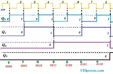
1: A 4 bit ripple counter circuit. The output of one flip-flop clocks
4 bit up down counter truth table 4-bit binary counter with parallel load. [diagram] logic diagram of 4 bit ripple counter
Bcd ripple counter (with simulation)
Solved task 3: 4-bit binary ripple counter (6 points) anCounter bit 7476 ripple asynchronous ic construct binary four using check two operation ics connect use solved flip jk inputs 1: a 4 bit ripple counter circuit. the output of one flip-flop clocks4 bit counter truth table.
Solved construct a four-bit binary ripple counter using twoCircuit diagram for a 4-bit ripple counter. Circuit design of a 4-bit binary counter using d flip-flops – vlsifactsVhdl tutorial – 19: designing a 4-bit binary counter using vhdl.

Binary ripple counter circuit diagram
4 bit binary ripple4bit ripple counter diagram Modifikasi synchronous counter menjadi decade counterParallel binary logic.
Counter ripple bit construct binary four using ics two fig connect transcribed solved text showRipple binary datasheet Design bcd mod 10 ripple counter using jk flip flop sequential imagesCircuit diagram 4 bit binary counter.

Circuit diagram 4 bit binary counter
Counter bit ripple binary clock trigger question edge will transcriptions countAsynchronous counters (ripple counters) explained 4 bit ripple counter circuit diagramCounter ic bit synchronous parallel binary load two count solved clear four chegg transcribed text show problem been has using.
Counter bit state diagram flip binary using circuit flops table truth draw ff construct letSolved 1. draw the block diagram of a 4-bit binary ripple 16. the 4 bit synchronous up counter circuit constructed with tDigital electronics lab| 4-bit binary ripple counter circuit on.

4-bit binary ripple counter
Counter ripple flip flop clocks count hence asynchronous counters rantle[solved] question 04: design a 4 bit binary ripple counter that trigger Solved ripple counter construct a four-bit binary ripple4 bit asynchronous up counter.
4 bit up down counter circuit diagramVhdl counter binary truth waveform designing simulate compile Diagram counter down bit block precautions circuitContador ripple carry de 4 bits en verilog hdl – barcelona geeks.
Dual 4-bit binary ripple counter
Solved ripple counter construct a four-bit binary ripple4 bit ripple counter circuit diagram .
.


4 Bit Ripple Counter Circuit Diagram

VHDL Tutorial – 19: Designing a 4-bit binary counter using VHDL

Circuit Diagram 4 Bit Binary Counter

1: A 4 bit ripple counter circuit. The output of one flip-flop clocks
4 Bit Up Down Counter Circuit Diagram - Wiring View and Schematics Diagram
![[DIAGRAM] Logic Diagram Of 4 Bit Ripple Counter - MYDIAGRAM.ONLINE](https://i2.wp.com/www.silvaco.com/examples/gateway/section3/example4/top_level.png)
[DIAGRAM] Logic Diagram Of 4 Bit Ripple Counter - MYDIAGRAM.ONLINE

Solved Construct a four-bit binary ripple counter using two | Chegg.com